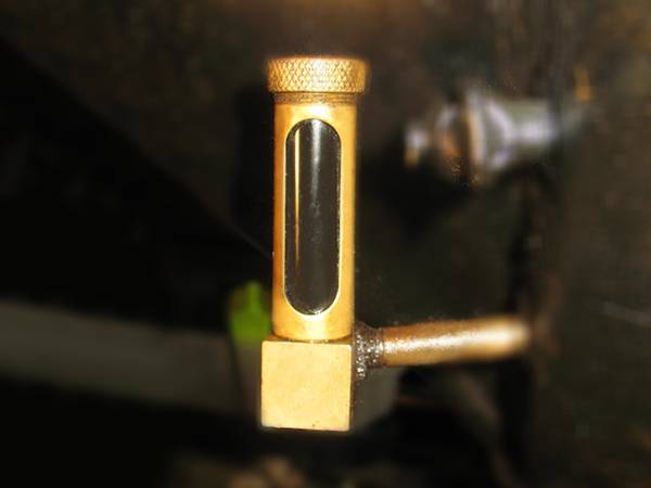
Oil level indicator structure diagram
- Body
- Protect pipe
- Nut
- Tube (Glass)
- Seal/Gasket
PRODUCTS
Oil level indicator combines the multiple advantages of tubular level gauges, planar level gauges and boiler level indicators.
It consists of two parts: the outer metal protective shell and the inner glass tube for liquid measurement. The metal shell protects the inner glass tube from damage without affecting the effect of visual observation. Meanwhile, it overcomes the weakness of general tubular level gauges, such as fragile, unstable, and unsafe.
It can replace planar level gauges to some extent due to its low costs than that of planar level gauges of the same properties.
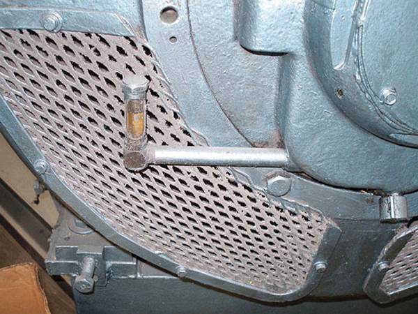
Oil level gauges are usually used for liquid level measurement of oil tanks in the petroleum industry and can be attached to any position of the tank by thread connection.
Oil level indicator
Features
| Range of Measurement | 0–1000 mm |
|---|---|
| Operating Pressure | 0.6–1.0 MPa |
| Operating Temperature | -10 °C to +180 °C |
| Body Material | ss304, ss316, brass, carbon steel |
| Gauge Glass Material | Glass |
| Way of Connection | Threaded connection |
Structure
Oil level indicator structure diagram
Application
Mica gaskets are commonly used in transparent level gauges and transparent type welded pad level gauges and act as protective shield for level gauges.
For oil tanks
For lubricating oil sample analysis

Something you want to ask?